Cleanroom HVAC system validation is a critical engineering activity for ensuring sustained compliance of controlled environments. From Installation Qualification (IQ), Operational Qualification (OQ) to Performance Qualification (PQ) for newly built cleanrooms, and through periodic revalidation during routine operations, every step directly impacts product yield and process safety. A cleanroom without rigorous validation, regardless of how high its hardware specifications may be, cannot guarantee actual cleanliness performance during operation. This article systematically analyzes six core aspects of cleanroom HVAC system validation based on the ISO 14644 series standards and international GMP regulations, providing comprehensive practical guidance for engineering professionals.
1. Overview of Cleanroom Validation Process
Cleanroom HVAC system validation is not a single-point inspection but rather a structured, systematic procedure. The internationally adopted validation framework originates from the pharmaceutical industry's GMP (Good Manufacturing Practice) regulations, dividing validation into three consecutive stages: Installation Qualification (IQ), Operational Qualification (OQ), and Performance Qualification (PQ)[1]. This three-stage validation model has been widely adopted across the semiconductor, optoelectronics, pharmaceutical, and food industries.
Installation Qualification (IQ)
The IQ stage confirms that all HVAC equipment and related components have been correctly installed according to design specifications and manufacturer recommendations. Inspection items include: whether the AHU/MAU installation positions, leveling, and vibration isolation measures comply with drawings; whether HEPA/ULPA filter models, grades, and installation orientations are correct; whether ductwork materials, dimensions, joint sealing, and insulation meet construction specifications; and whether temperature/humidity sensors, differential pressure transmitters, and other instruments have proper installation locations and calibration records. The IQ stage also requires confirmation that all equipment nameplates, factory test reports, and calibration certificates are properly archived[2].
In engineering practice, the most commonly overlooked aspect during the IQ stage is ductwork cleanliness verification. Metal debris, sealant residue, or insulation fibers remaining from construction can all become particulate contamination sources once the system starts up. Therefore, the IQ stage should include visual inspection and cleanliness verification of ductwork interiors, with swab testing conducted when necessary to confirm cleanliness.
Operational Qualification (OQ)
The OQ stage is performed after equipment installation is complete, validating the HVAC system's operational performance within design condition ranges. Test items cover: whether the AHU supply and return airflow volumes meet design values; whether pressure differential gradients across zones comply with specifications; whether temperature and humidity control can operate stably within the allowable deviation range from setpoints; and whether automatic control system logic functions (such as pressure differential alarms, high temperature protection, and interlock controls) operate correctly[3].
OQ testing is typically performed when the cleanroom is in as-built or at-rest conditions -- meaning the HVAC system is operating but no process equipment is running and no personnel are active. Test results under these conditions reflect the HVAC system's inherent performance baseline, providing a comparison benchmark for subsequent dynamic validation.
Performance Qualification (PQ)
The PQ stage is conducted under operational (dynamic) conditions with process equipment installed and personnel performing normal work, validating whether the cleanroom can continuously meet cleanliness and environmental control requirements in actual use scenarios. PQ test scope includes: ISO 14644-1 particle count verification, airflow pattern visualization, long-term temperature/humidity stability recording, and environmental monitoring system alarm function verification.
It is worth emphasizing that ISO 14644-1:2015 explicitly defines three test states[4]: As-built refers to a cleanroom facility that is complete but without equipment or personnel; At-rest means equipment is installed and can operate but no personnel are present; Operational indicates the facility is in normal operating condition, including personnel and process activities. Industry practice typically requires as-built cleanliness to be at least one class better than the target level, ensuring sufficient safety margin during dynamic operation.
2. ISO 14644-3 Cleanliness Testing Methods
Cleanliness testing is the core item of cleanroom validation. ISO 14644-3:2019 specifies testing methods, sampling strategies, and acceptance criteria in detail[5], serving as the primary reference standard for engineering professionals conducting tests.
Particle Count Testing Procedures
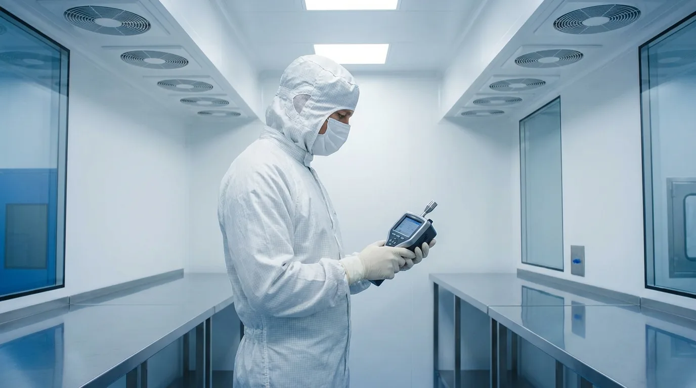
Particle count testing uses Discrete Particle Counters (DPC) or Laser Particle Counters (LPC) to measure airborne particle concentrations within specific size ranges. Instrument selection depends on the target ISO class: ISO Class 5 and above typically use optical particle counters with a flow rate of 28.3 L/min (1 CFM), while ISO Class 3 and below may require Condensation Nucleus Counters (CNC) to detect ultrafine particles below 0.1 um[6].
The minimum sampling volume for each sample is calculated according to ISO 14644-1 Annex A. The basic principle is that at the maximum allowable concentration for the target class, a single sample should detect at least 20 particles to ensure statistical reliability. For ISO Class 5 (0.5 um particle size, limit of 3,520 particles/m3), the minimum sampling volume is 2 L (0.002 m3), though in practice, sampling typically lasts at least 1 minute to obtain stable readings.
Number and Placement of Sampling Points
The minimum number of sampling points NL specified by ISO 14644-1:2015 is based on 95% confidence interval statistical requirements, calculated using the formula[4]:
Where A is the cleanroom area (m2). For example, a 100 m2 cleanroom requires at least 10 sampling points; a 400 m2 cleanroom requires at least 20 sampling points. Sampling points should be evenly distributed across the cleanroom work area, with particular attention to: locations near return air or exhaust outlets (where particles may accumulate), near process equipment (local particle generation sources), areas with frequent personnel activity, and airflow dead zones or vortex regions.
Acceptance Criteria and Statistical Analysis
After sampling is complete, the ISO 14644-1 acceptance procedure is as follows: First, the average particle concentration at each sampling point must not exceed the maximum allowable concentration for the target class; Second, when the number of sampling points is between 2 and 9, the 95% confidence interval upper limit (UCL) of all sampling point averages must be calculated, and this upper limit must also not exceed the maximum allowable concentration. The formula is[4]:
Where X-bar is the arithmetic mean of average concentrations across all sampling points, S is the standard deviation, and t is the t-distribution value corresponding to NL-1 degrees of freedom (95% one-sided confidence interval). UCL calculation is not required when the number of sampling points is 1 or exceeds 9.
Test Instrument Calibration
The accuracy of particle counters directly affects the credibility of test results. ISO 21501-4 specifies calibration methods for optical particle counters[7]. Instruments should be calibrated at least annually by laboratories accredited to ISO/IEC 17025. Calibration items include: flow rate accuracy (plus or minus 5%), counting efficiency (for each size channel), size resolution, and False Count Rate. Before field testing, a Zero Count Test should also be performed on the instrument to ensure the sampling tubing has no leaks or residual contamination.
3. HVAC System Performance Validation Items
Beyond cleanliness testing, cleanroom HVAC system performance validation covers measurement and verification of multiple environmental parameters. These items are performed according to ISO 14644-3:2019 and IEST-RP-CC006.3 specifications[8].
Airflow Volume and Air Change Rate
Airflow volume testing uses a Balometer to measure the actual airflow at each supply air outlet (FFU or duct outlet), which is then summed to calculate the cleanroom's total supply airflow and air changes per hour (ACH). For unidirectional (laminar flow) cleanrooms, multi-point velocity measurements are taken at the FFU discharge face using a hot-wire anemometer to confirm average velocity (typically 0.3-0.5 m/s) and uniformity metrics. Uniformity is generally expressed as the percentage deviation of each measurement point velocity from the average velocity, required to be within plus or minus 20%[5].
Non-unidirectional (turbulent flow) cleanrooms focus on confirming air change rates. Typical air change rates for ISO Class 7 are 30 to 60 per hour, and for ISO Class 8, 10 to 25 per hour. Actual air change rates should be determined through engineering calculations based on room particle generation rates, personnel density, and equipment heat dissipation, rather than relying solely on standard recommended values[9].
Room Pressurization and Pressure Differential Gradients
Pressure differential testing confirms the pressure gradients between zones of different cleanliness classes. Testing uses high-precision micro-manometers (resolution of 0.1 Pa or better) to measure pressure differentials of each zone relative to corridors, airlocks, or adjacent areas. ISO 14644-4 recommends maintaining 5 to 20 Pa pressure differentials between adjacent cleanliness classes[10], with higher cleanliness zones at higher pressure than lower ones.
Pressure differential testing should be conducted under steady-state conditions with doors closed, while also recording pressure differential changes and recovery times during door opening. In semiconductor fabs, airlock design is particularly critical -- entry and exit doors must not open simultaneously (interlock control), and the airlock pressure should be between the two adjacent zones. For pharmaceutical cleanrooms, EU GMP Annex 1 requires pressure differentials of at least 10 Pa between clean zones[11].
Temperature and Humidity Uniformity
Temperature and humidity testing involves multi-point measurements at the cleanroom working height (typically 900 to 1,200 mm above floor level). Testing uses calibrated temperature/humidity recorders (accuracy requirements: temperature plus or minus 0.1 degrees C, relative humidity plus or minus 1% RH) for continuous recording over at least 1 hour under steady-state conditions. Measurement point placement should cover the cleanroom's center area, near walls, below supply outlets, and near return air outlets.
Temperature uniformity is typically assessed by the maximum deviation of each measurement point temperature from the setpoint. General cleanroom temperature control precision is plus or minus 1 to 2 degrees C, while semiconductor lithography areas may require plus or minus 0.1 degrees C or stricter. Relative humidity control precision is generally plus or minus 2% to 5% RH, depending on process requirements.
Airflow Pattern Testing (Smoke Testing)
Airflow visualization testing uses a smoke generator to release visible smoke or tracer gas to observe airflow patterns within the cleanroom. For unidirectional flow cleanrooms, this test confirms whether airflow maintains a parallel, downward flow pattern without significant vortices or reverse flow regions; for non-unidirectional flow cleanrooms, it confirms whether the airflow path between supply and return is reasonable, without dead zones or short-circuiting[5].
Smoke testing should be recorded on video as part of the validation documentation. Areas requiring particular attention include: the interface between the FFU supply face and walls (boundary effects), above and around process equipment (thermal disturbance effects), airflow changes during door opening, and disruption to local airflow fields from personnel movement. Results from these dynamic tests often serve as important bases for optimizing HVAC system design and operating parameters.
Need professional technical support for cleanroom HVAC system validation? Contact our engineering team for validation solutions compliant with ISO 14644 standards.
4. HEPA/ULPA Filter Integrity Testing
HEPA and ULPA filters are the last and most critical filtration line of defense in cleanroom HVAC systems. Installed filter leak testing confirms that there are no leaks in the filter media, frame joints, or sealing gaskets, making it a mandatory item in as-built validation.
DOP/PAO Aerosol Generation and Detection
Filter integrity testing is performed according to ISO 14644-3:2019 Annex B.7 and IEST-RP-CC006.3 specifications[8]. Testing uses an aerosol generator to release polydisperse test aerosol upstream of the filter. Traditionally, DOP (dioctyl phthalate) was used, but due to health concerns, PAO (poly-alpha olefin, i.e., Emery 3004 or equivalent) has largely replaced it[12]. Upstream aerosol concentration is typically controlled between 10 and 100 ug/L.
The detection end uses an aerosol photometer to measure aerosol penetration downstream of the filter. The photometer sensitivity must be capable of detecting penetration rates above 0.001%, corresponding to the testing requirements for HEPA H14 (efficiency 99.995%).
Leak Scan Test
The core step of integrity testing is the leak scan. The operator holds the photometer's sampling probe, scanning the entire filter area and frame seals at a speed not exceeding 5 cm/s, at a distance of approximately 2.5 to 3.8 cm from the downstream face of the filter, following a systematic path[5]. The scanning path should cover: the entire pleated area of the filter, the sealing strips between the filter and frame, and the seals between the frame and ceiling support structure.
The acceptance criterion is typically: penetration at any single scan point must not exceed 0.01% (corresponding to HEPA H14 class). If a leak point is found, its location must be marked and repaired. The repairable leak area generally must not exceed 3% of the total area of a single filter -- exceeding this limit requires filter replacement. For ULPA class filters, acceptance criteria are stricter, with single-point penetration limits potentially as low as 0.001% or lower.
Filter Replacement Indicators
During use of HEPA/ULPA filters, as particles accumulate through interception, filter pressure drop gradually increases. Pressure drop monitoring is the primary indicator for determining filter replacement timing. A typical HEPA H14 filter has an initial pressure drop of approximately 120 to 250 Pa. When the pressure drop rises to the terminal pressure drop (generally set at 2 times the initial pressure drop, approximately 400 to 600 Pa), replacement should be performed[9].
Beyond pressure drop, the following conditions should also warrant filter replacement consideration: integrity testing reveals irreparable leaks; the filter appearance shows obvious discoloration, moisture, or structural damage; cleanliness monitoring data shows sustained abnormal increases in downstream particle concentrations. In practice, filter service life is greatly affected by environmental conditions -- pre-filter efficiency, room particle generation rates, and operating hours all influence HEPA filter replacement cycles, which generally range from approximately 3 to 5 years.
5. Environmental Monitoring System Design
The Environmental Monitoring System (EMS) is the long-term assurance mechanism for maintaining a controlled state after cleanroom validation acceptance. A comprehensive EMS should integrate particle monitoring, temperature/humidity recording, pressure differential monitoring, and alarm management functions.
Continuous Particle Monitoring
For ISO Class 5 and above critical process areas, continuous particle monitoring has become an industry standard configuration. The monitoring system consists of remote particle sensors distributed at key locations throughout the cleanroom, manifold sampling systems, or standalone particle counters, collecting and analyzing data in real-time through central control software[13].
Monitoring point placement should be based on risk assessment, with key coverage of: critical exposure areas of process equipment (such as semiconductor wafer transfer paths), below HEPA filter supply faces, near return air outlets, and along personnel entry/exit routes. Monitoring frequency depends on industry requirements -- semiconductor fabs typically conduct 24-hour continuous monitoring, while pharmaceutical cleanrooms follow EU GMP Annex 1 recommendations for continuous monitoring at minimum during each production batch[11].
Temperature and Humidity Recording System
The temperature and humidity recording system consists of distributed sensors, data acquisition units, and a central server. For FDA-regulated pharmaceutical cleanrooms, this system must comply with 21 CFR Part 11 electronic records and electronic signatures requirements[14], including: non-tamperable data timestamps, user access control with audit trails, and data backup and disaster recovery mechanisms.
Sensor density depends on cleanroom area and environmental uniformity requirements. The general principle is: one temperature/humidity monitoring point per 20 to 50 m2. Recording intervals are typically set at 1 to 5 minutes, with data retention periods of at least the product shelf life plus 1 year, or at least 3 years, per regulatory requirements. Temperature sensors should be periodically calibrated (at least annually), with calibration standards traceable to national metrology standards.
Pressure Differential Monitoring and Trend Analysis
Pressure differential monitoring is the real-time defense line for maintaining cleanroom particle control. High-precision micro-differential pressure transmitters (measurement range typically 0-100 Pa, accuracy plus or minus 0.5 Pa) are installed on partition walls between adjacent zones, transmitting signals to the BMS (Building Management System) or a standalone EMS platform. Real-time display and historical trend analysis of pressure differential data help detect system anomalies early.
Alarm configuration is the core of pressure differential monitoring. Typical alarm levels include: Alert (pressure differential approaching the lower limit but not yet out of specification) and Action (pressure differential has fallen below the qualified standard). For example, if the design pressure differential is 15 Pa, the alert may be set at 12 Pa and the action limit at 10 Pa. Pressure differential trend analysis can also reveal signs of system aging or maintenance needs -- filter blockage causing airflow reduction, or aging door sealing gaskets causing increased leakage can both be detected in pressure differential trends.
Alarm Management and Event Response
The alarm management of environmental monitoring systems should follow clearly defined tiering and response procedures. All alarm events must be automatically recorded, including occurrence time, duration, affected area, and duty personnel response actions. For deviations exceeding the action limit, a deviation investigation procedure must be initiated, analyzing root causes and developing Corrective and Preventive Actions (CAPA)[11].
6. Periodic Revalidation and Maintenance Scheduling
Cleanroom HVAC system validation is not a one-time effort. ISO 14644-2:2015 explicitly specifies periodic revalidation requirements and recommended intervals[15], ensuring system performance continues to meet specifications throughout the entire lifecycle.
ISO 14644-2 Revalidation Intervals
ISO 14644-2:2015 recommended revalidation intervals are as follows: For particle count testing, ISO Class 5 and above recommend full validation every 6 months, while ISO Class 6 through ISO Class 9 recommend every 12 months. Airflow velocity/volume testing is recommended every 12 months. Pressure differential testing is recommended every 12 months. However, if the cleanroom is equipped with a continuous monitoring system that is continuously operating, the revalidation frequency may be adjusted based on monitoring data trend analysis.
Note that EU GMP Annex 1 (2023 revision) imposes stricter requirements for pharmaceutical cleanrooms: Grade A and Grade B areas require continuous particle monitoring under dynamic conditions, and Grade C areas recommend monthly static particle counts[11]. The FDA's Guidance for Industry: Sterile Drug Products Produced by Aseptic Processing also requires periodic environmental monitoring validation for aseptic processing environments[16].
Maintenance Schedule
A systematic maintenance schedule is the cornerstone of preventive maintenance. The following are typical maintenance items and recommended frequencies for cleanroom HVAC systems:
Daily Maintenance Items: Confirm pressure differential readings in each zone are within normal range; review the environmental monitoring system for unresolved alarms; visually confirm cleanroom entry/exit personnel controls and gowning procedure compliance.
Weekly Maintenance Items: Check pre-filter pressure drop changes; confirm temperature/humidity recording data stability and trends; inspect condensate drain lines for proper flow.
Monthly Maintenance Items: HEPA/ULPA filter pressure drop recording and trend analysis; AHU supply fan vibration measurement and recording; chilled water valve and controller function confirmation; emergency backup system function testing.
Annual Maintenance Items: Comprehensive HVAC system performance validation (airflow volume, pressure differentials, temperature/humidity); HEPA/ULPA filter integrity testing; calibration of all environmental monitoring instruments; AHU internal cleaning and coil washing; ductwork cleanliness inspection; automatic control system logic and sensor verification[9].
Standard Operating Procedures (SOP) for Anomaly Handling
The anomaly handling SOP for cleanroom HVAC systems should cover the following common scenarios:
- Abnormal Pressure Differential Drop: Immediately confirm whether doors are fully closed, check whether airflow volume is normal, and verify whether the exhaust system has abnormally increased. If pressure differential cannot recover within the specified time, initiate a product risk assessment for the affected area.
- Particle Count Exceedance: Confirm whether monitoring instruments are functioning normally, rule out human interference factors, then initiate a deviation investigation. Trace possible contamination sources including filter leaks, poor door sealing, and personnel gowning procedure deficiencies.
- Temperature/Humidity Out of Specification: Check HVAC equipment operating status, chilled water supply temperature and flow rate, and whether control valves are functioning properly. Assess the potential impact on processes or product quality during the exceedance period.
- HVAC Equipment Failure: Activate backup equipment (if configured), notify the maintenance team for emergency repair, and assess whether process activities in the affected area need to be stopped. After equipment recovery, conduct simplified validation to confirm environmental parameters have returned to normal.
All anomaly events should be recorded in deviation log forms. After Root Cause Analysis (RCA), corrective measures and preventive actions (CAPA) should be developed, with implementation effectiveness tracked. This deviation management mechanism is one of the core elements of the GMP quality system.
Conclusion
Cleanroom HVAC system validation and maintenance is a systematic endeavor combining engineering technology, quality management, and regulatory compliance. From establishing the system's performance baseline through IQ/OQ/PQ three-stage validation, to confirming air quality through ISO 14644-3 cleanliness testing, ensuring filtration efficiency through HEPA filter integrity testing, providing continuous real-time assurance through environmental monitoring systems, and maintaining long-term system stability through periodic revalidation and preventive maintenance -- every link is interconnected and indispensable. Facing increasingly stringent international regulatory requirements and ever-improving process precision demands, only through rigorous engineering execution of each validation and maintenance task can we provide solid quality assurance for clean manufacturing environments.