Cleanroom technology, established by the U.S. Federal Standard 209 series in the 1960s, has become an indispensable infrastructure for the semiconductor, optoelectronics, pharmaceutical, and biotechnology industries. In 2001, the ISO 14644 series officially replaced Fed-Std-209E[1], becoming the authoritative global standard for cleanroom design and verification. This article provides an in-depth analysis of the core considerations for cleanroom HVAC system design from an engineer's perspective.
1. ISO 14644-1 Cleanliness Classification System
ISO 14644-1:2015 defines nine cleanliness classes (ISO Class 1 through ISO Class 9), classified based on the concentration of airborne particles greater than or equal to a specified particle size[2]. The core formula is:
Where Cn is the maximum permitted particle concentration (particles/m³), N is the ISO class number, and D is the considered particle size (μm). The exponent 2.08 is based on empirical regression of particle size distribution[3].
Taking ISO Class 5, commonly used in semiconductor front-end processes, as an example: at 0.5 μm particle size, the maximum permitted concentration is 3,520 particles/m³, equivalent to Class 100 under the former Fed-Std-209E. Advanced EUV lithography process areas may even require ISO Class 3 or higher, imposing extremely stringent demands on the HVAC system's filtration efficiency and airflow uniformity.
2. Airflow Patterns: Unidirectional and Non-Unidirectional Flow
The airflow pattern of a cleanroom directly determines particle removal efficiency and is a core design decision for the HVAC system. ISO 14644-4 classifies airflow patterns into two main categories[4]:
Unidirectional Airflow
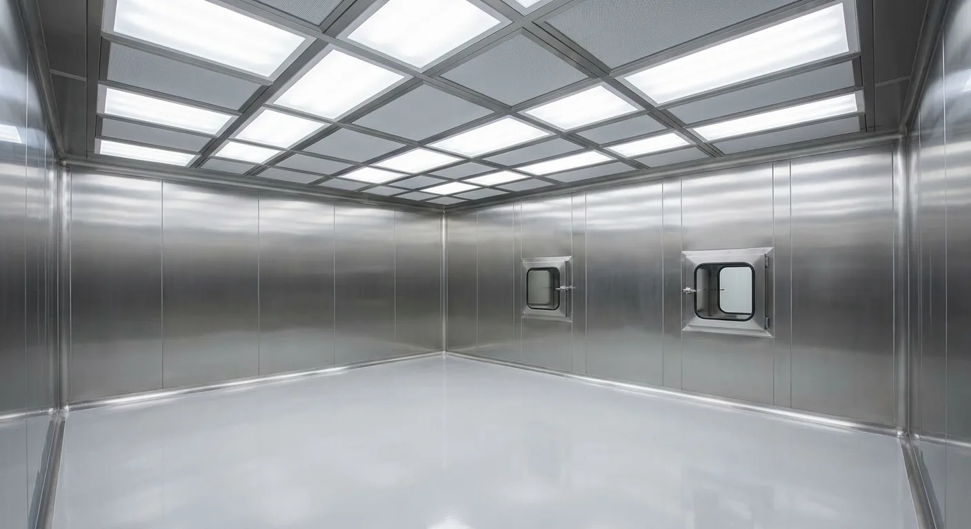
Also known as laminar flow, air flows uniformly and in parallel through the entire clean zone, with particles carried to the return air outlets along the airflow direction. Suitable for ISO Class 5 and above. Typical ceiling supply air configurations require FFU (Fan Filter Unit) coverage of 60% to 100%, with airflow velocities of approximately 0.3 to 0.5 m/s[5].
In semiconductor wafer fab practice, we typically design FFU coverage at 80% or above to ensure stable unidirectional airflow even when equipment operation generates thermal disturbances. High coverage rates mean enormous air supply volumes and energy consumption — the HVAC system of a typical 300mm wafer fab cleanroom can account for 30% to 40% of the total plant electricity consumption[6].
Non-Unidirectional Airflow
The traditional turbulent flow method uses fewer supply air outlets to deliver clean air into the room, reducing particle concentration through the mixing dilution principle. Suitable for ISO Class 6 through ISO Class 8, with air change rates ranging from 20 to 60 times per hour depending on the class[7]. Although cleanliness performance is inferior to unidirectional flow, both construction costs and operating energy consumption are significantly reduced.
3. Filtration System Design: HEPA and ULPA
High Efficiency Particulate Air (HEPA) and Ultra Low Penetration Air (ULPA) filters are core components of cleanroom HVAC systems. According to EN 1822-1:2019 and ISO 29463 standards[8]:
- HEPA H13: Filtration efficiency at MPPS (Most Penetrating Particle Size, approximately 0.12–0.25 μm) ≥ 99.95%
- HEPA H14: MPPS filtration efficiency ≥ 99.995%
- ULPA U15: MPPS filtration efficiency ≥ 99.9995%
- ULPA U16: MPPS filtration efficiency ≥ 99.99995%
Cleanrooms of ISO Class 5 and above typically use HEPA H14 filters, while ISO Class 3 and below require ULPA grade filters. Filter selection must consider not only efficiency but also initial pressure drop and final pressure drop — HEPA H14 initial pressure drop is approximately 120–250 Pa, with the final pressure drop limit generally set at 450–600 Pa[9]. This pressure drop directly affects FFU or AHU fan selection and energy consumption.
4. Pressure Differential Control Strategy
Cleanroom pressure differential control is the first line of defense against external particle intrusion. ISO 14644-4 recommends maintaining a positive pressure differential of at least 5 to 20 Pa between zones of different cleanliness classes, with higher cleanliness zones at higher pressure than lower ones[10].
In engineering practice, the stability of pressure differential control is often more critical than absolute values. Personnel entry and exit, equipment movement, and door opening and closing all cause pressure fluctuations. We typically employ the following strategies:
- Installation of airlocks as buffers between zones of different cleanliness classes
- Variable frequency air supply systems combined with high-precision pressure differential sensors for dynamic pressure compensation
- Door interlock control to prevent adjacent airlock doors from opening simultaneously
- Pressure relief dampers to prevent excessive pressure differentials that make doors difficult to open
5. Temperature and Humidity Control Precision
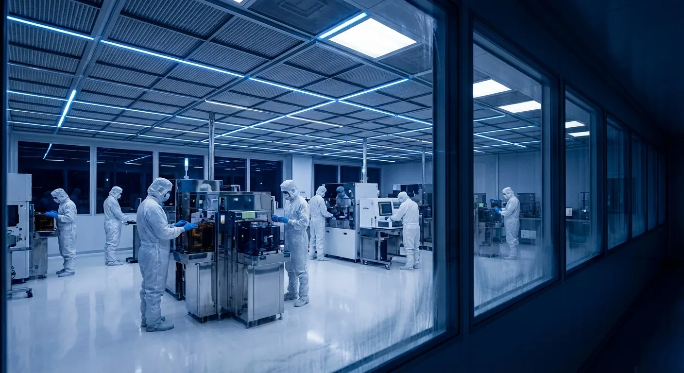
Semiconductor processes demand extremely high temperature and humidity control precision. For example, in an advanced process lithography area, typical temperature control requirements are 23 ± 0.1°C, with relative humidity control at 45 ± 2% RH[11].
This presents multiple challenges for HVAC system design: reheat control after cooling and dehumidification must be precise, supply air temperature uniformity must be good, and the control loop response speed must be fast enough to suppress transient disturbances caused by process equipment heat dissipation. In practice, we install reheat coils or dry cooling coils downstream of the air handling unit (AHU/MAU), combined with PID controllers for precision regulation.
6. Verification and Monitoring: From Design to Operation
According to ISO 14644-3:2019, cleanroom verification is divided into three states[12]:
- As-built: Facility completed, equipment and personnel not yet moved in
- At-rest: Equipment installed and operating, but no personnel activity
- Operational: Normal operating state, including personnel and process activities
As-built and at-rest verification confirm the HVAC system's design performance, while operational verification reflects cleanliness performance under actual use conditions. The gap between the three often represents the safety margin that engineering design must account for — industry convention typically requires as-built cleanliness to be at least one class better than the target class[13].
Additionally, ISO 14644-2:2015 specifies requirements for periodic cleanliness monitoring, recommending a complete particle count verification every six months for ISO Class 5 and below[14]. The implementation of continuous monitoring systems has become standard practice in advanced manufacturing facilities.
Conclusion
Cleanroom engineering is one of the most technically demanding areas in the field of refrigeration and air conditioning. From understanding and applying ISO 14644 standards to the integrated design of airflow patterns, filtration systems, pressure differential control, and temperature/humidity precision, every aspect requires a deep engineering theory foundation and extensive practical experience. As semiconductor processes continue to shrink and biotech/pharmaceutical regulations become increasingly stringent, cleanroom HVAC system design standards will only continue to rise. Only through continuous advancement can we meet these challenges.