For food manufacturers, the refrigeration and air conditioning system is not merely a facility for maintaining a comfortable environment, but a critical infrastructure for ensuring food safety and regulatory compliance. According to the Good Hygiene Practice (GHP) guidelines[1] promulgated by Taiwan's Ministry of Health and Welfare, food factory processing, preparation, packaging, and storage areas must maintain appropriate temperature and humidity conditions, and air quality must meet product-specific requirements. Furthermore, HACCP-certified food factories must provide reliable and traceable temperature control capability at every Critical Control Point (CCP). This article systematically analyzes six core aspects of food factory HVAC design from a professional refrigeration and air conditioning engineering perspective — from understanding the regulatory framework, cleanliness zoning and airflow design, temperature/humidity control technology, blast freezing equipment selection, refrigerant system evaluation, to factory energy management and waste heat recovery integration strategies — providing food manufacturers with a complete engineering guide from planning to implementation.
1. Regulatory Framework for Food Factory HVAC Design (GHP, HACCP)
Food factory HVAC design is not purely an engineering problem, but a compliance engineering exercise that must be conducted within the regulatory framework. Taiwan's food safety regulatory system is built on the Food Safety and Sanitation Management Act, under which the GHP guidelines[1] and HACCP system standards define specific requirements for food factory environmental control. HVAC system design must start from these regulatory requirements rather than simply following engineering conventions.
GHP Basic Requirements for Factory Environments
GHP guidelines clearly stipulate that food manufacturing premises should have effective ventilation and HVAC facilities to prevent excessive indoor temperatures, steam condensation, and odor retention. Specific requirements include: work areas should maintain appropriate temperature and relative humidity to prevent food contamination; exhaust emissions should avoid polluting adjacent work areas; air intake openings should have appropriate filtration devices to prevent dust, pests, and foreign objects from entering. These seemingly simple provisions actually have far-reaching impacts on HVAC system design — they require engineering design to satisfy not only temperature requirements but also airflow direction control, filtration grade, and positive/negative pressure relationships.
HACCP System Key Requirements for Temperature Control
For designated food business categories (such as meat processing, seafood processing, dairy processing, boxed meal production, etc.), the implementation of HACCP systems further elevates temperature control requirements. The core concept of HACCP is to identify Critical Control Points (CCPs) in the manufacturing process and establish critical limits and monitoring methods for each CCP. In the context of refrigeration and air conditioning engineering, this means:
- Cooling Process CCP: Cooked food cooling must bring center temperature from 60 degrees C to below 7 degrees C within the specified time; the HVAC system must provide sufficient cooling capacity to support this time requirement
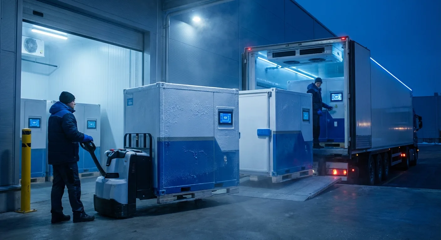
- Refrigerated Storage CCP: Cold storage must maintain 0 to 7 degrees C, frozen storage must maintain below -18 degrees C, and temperature fluctuation must be controlled within +/-2 degrees C
- Processing Environment CCP: Certain food processing areas (such as raw seafood, ready-to-eat food) must maintain temperatures of 15 to 20 degrees C to suppress microorganism growth rates
- Temperature Monitoring and Recording: All CCP point temperatures must have continuous monitoring and automatic recording functions linked to alarm systems, requiring the HVAC control system to integrate temperature monitoring architecture
ISO 22000 and International Standards Alignment
As international markets increasingly demand food safety management, more Taiwan food factories are implementing ISO 22000:2018 Food Safety Management Systems[2]. ISO 22000 integrates HACCP principles with the ISO management system framework, with more comprehensive requirements for Prerequisite Programs (PRPs), including factory environment, air quality, and water quality management. As the core facility for factory environmental control, the HVAC system's design documents, maintenance plans, and calibration records must all be incorporated into the ISO 22000 document management system.
2. Cleanliness Zoning and Airflow Direction Design (Positive vs Negative Pressure)
Food factory spatial planning must zone based on the microbiological risk level of products, and HVAC system airflow design is the engineering means to maintain cleanliness differences between zones. Correct airflow direction design can effectively prevent cross-contamination, representing the core design element that distinguishes food factory HVAC from general commercial HVAC.
Cleanliness Zoning Principles
Based on food factory process characteristics and risk assessment, factory areas are typically divided into the following cleanliness levels:
- General Work Area: Raw material warehouses, outer packaging areas, finished product warehouses, etc., with lower air particulate control requirements but still requiring adequate ventilation
- Semi-Clean Work Area: Raw material pre-processing areas, heating/cooking areas, etc., requiring basic air filtration (pre-filter G4 grade or above) and temperature control
- Clean Work Area: Cooling areas, portioning areas, inner packaging areas, etc. — the high-risk stage where food is exposed to the environment, requiring higher-grade air filtration (medium-efficiency filter F7 to F9 grade) and strict temperature/humidity control
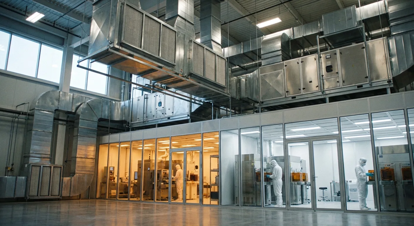
- High-Cleanliness Work Area: Final filling and packaging areas for ready-to-eat foods; some products (such as raw seafood, fresh meal boxes) may require near-cleanroom-level air quality (HEPA filtration), with airborne bacterial counts controlled within specified ranges
Positive Pressure Gradient and Airflow Direction Design
The core principle of food factory airflow design is "flow from clean areas to less clean areas," achieved through establishing positive pressure gradients. The highest cleanliness zone maintains the highest positive pressure, with air pressure decreasing progressively from high-cleanliness zones to low-cleanliness zones, ensuring air flows only from clean areas to less clean areas, not in reverse[3]. Typical positive pressure design values are: high-cleanliness work area maintains +15 to +25 Pa positive differential relative to corridors, clean work area maintains +10 to +15 Pa, semi-clean work area maintains +5 to +10 Pa. The pressure differential between zones should be established and maintained through precise balancing of supply and exhaust air volumes.
Notably, certain special areas require negative pressure design. For example: raw material thawing areas (to prevent moisture and odor from thawing from spreading to other areas), waste temporary storage areas (to prevent odors and microorganisms from spreading outward), and specific high-dust operation areas (such as flour mixing areas). Exhaust from these negative pressure areas must be appropriately treated before discharge to avoid affecting other factory areas or the surrounding environment.
Airflow Organization and Supply/Exhaust Methods
In clean and high-cleanliness work areas, airflow organization design is equally important. Generally, a top-down unidirectional airflow (or near-unidirectional airflow) pattern is adopted, with supply outlets at the ceiling and exhaust outlets on walls near the floor, allowing clean air to enter from above, carry away suspended particles, and exit from below. The number of air changes varies by zone level: semi-clean work areas approximately 10 to 15 changes per hour, clean work areas approximately 15 to 25 changes per hour, and high-cleanliness work areas can reach 25 to 40 changes per hour. Access control systems and air locks are also important auxiliary measures for maintaining zone pressure differentials.
3. Processing Area Temperature/Humidity Control and Condensation Prevention
Temperature and humidity control in food processing areas directly affects product quality and microbiological safety, and condensation is the number one environmental hygiene hazard in food factories. Condensation dripping onto food not only causes product rejection but may also trigger microbiological contamination and food safety incidents. HVAC system design must address the condensation problem at its source rather than relying on after-the-fact cleaning measures.
Temperature and Humidity Design Standards
Temperature and humidity design standards differ significantly across different types of food processing areas and must be comprehensively determined based on product characteristics, process requirements, and regulatory requirements:
- Meat cutting and packaging area: Temperature 10 to 15 degrees C, relative humidity 50% to 65%, to suppress microorganism proliferation and maintain meat color
- Seafood processing area: Temperature 15 to 18 degrees C, relative humidity 60% to 70%, balancing low-temperature environment with worker comfort
- Bakery cooling area: Temperature 20 to 25 degrees C, relative humidity 40% to 55%; excessive humidity causes products to absorb moisture, affecting texture and shelf life
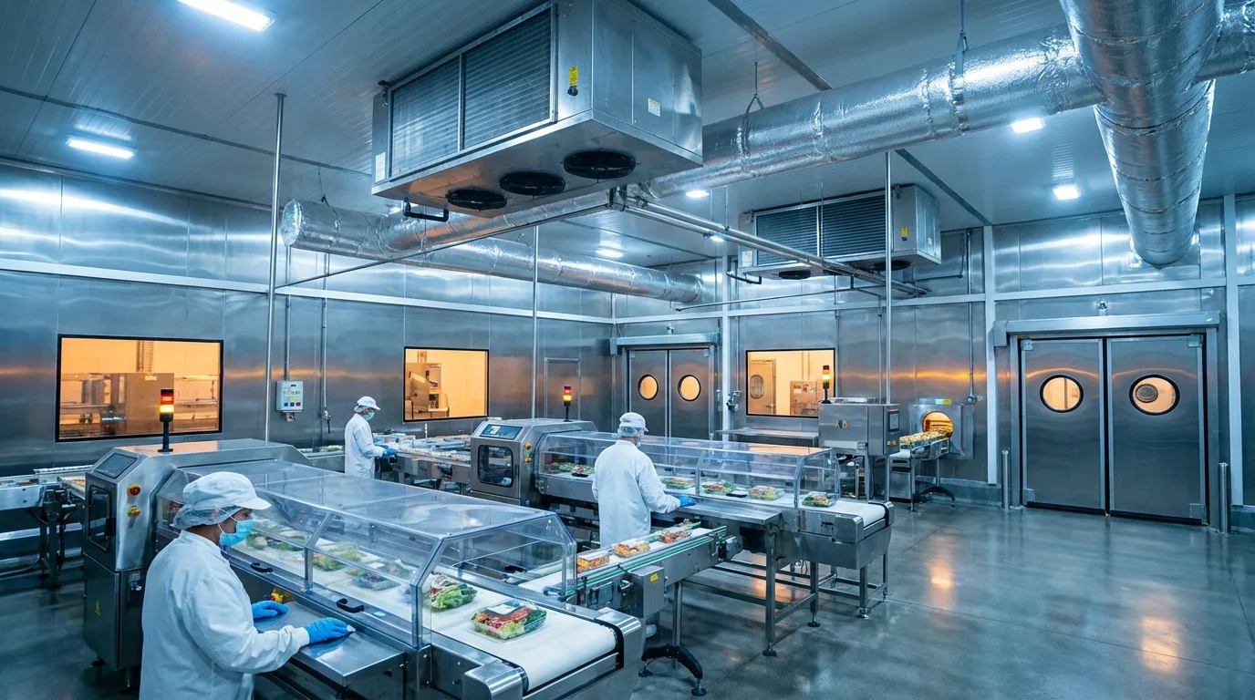
- Ready-to-eat food filling area: Temperature 18 to 22 degrees C, relative humidity 50% to 60%; the most sensitive stage of food exposure, with the highest temperature/humidity stability requirements
Condensation Causes and Prevention Engineering
Condensation occurs when surface temperature falls below the dew point temperature of surrounding air. In food factories, condensation-prone locations include: ceilings and walls near cold storage doors (cold/warm air interfaces), pipe wall surfaces where refrigeration pipes pass through non-refrigerated areas, processing area ceilings (especially above cooking processes producing large amounts of steam), and exterior walls and roof interiors (particularly severe during Taiwan's southern high-temperature, high-humidity summers).
Condensation prevention engineering strategies are multi-layered: First, at the building level, strengthen the thermal insulation performance of the building envelope (roof and exterior wall insulation U-values should be below 0.7 W/m2K), and install appropriate thermal break constructions at cold/warm zone interfaces; Second, at the HVAC level, precisely control the dew point temperature in each zone, designing supply air temperature to ensure that all interior surface temperatures are at least 3 degrees C above the air dew point temperature as a safety margin[4]; Third, at the dehumidification level, high-humidity process areas should be equipped with independent dehumidification systems (such as desiccant wheel dehumidifiers) to control air dew point temperature within safe ranges; Finally, at the piping level, insulation thickness for all low-temperature pipes must be confirmed through condensation calculations, and insulation material joints and penetration points must be properly sealed to prevent moist air from infiltrating the insulation layer.
Dedicated Outdoor Air System (DOAS) for Independent Temperature/Humidity Control
Traditional HVAC systems use a single coil to simultaneously handle sensible and latent heat (controlling both temperature and humidity), but in food factories, temperature and humidity control requirements often do not correspond proportionally. For example, seafood processing areas require low temperatures but relatively high humidity; using traditional cooling-dehumidification would over-dehumidify, necessitating re-humidification and causing energy waste. Adopting a Dedicated Outdoor Air System (DOAS) can effectively solve this problem: a dedicated Makeup Air Unit (MAU) handles the latent heat load of outdoor air (dehumidifying to the target dew point), while zone Air Handling Units (AHUs) handle each zone's sensible heat load (adjusting temperature to the target value). Both are independently controlled, enabling more precise satisfaction of the differentiated temperature/humidity requirements across food factory zones.
Need professional planning for food factory refrigeration and HVAC systems? Contact our engineering team for GHP-compliant engineering design solutions.
4. Blast Freezing Equipment Selection: Spiral, Tunnel, and Fluidized Bed
Individual Quick Freezing (IQF) is the most demanding refrigeration process stage in food factories. The purpose of blast freezing is to pass the food's center temperature through the maximum ice crystal formation zone (-1 to -5 degrees C) in the shortest time, creating small, uniformly distributed ice crystals that preserve the food's cellular structure, texture, and nutritional value. Different product types require different blast freezing equipment, and equipment selection directly affects product quality, production efficiency, and energy consumption.
Spiral Freezer
Spiral freezers feature a spiral conveyor belt stacked in layers within an insulated enclosure. Products enter at the bottom and travel along the spiral belt upward (or downward) to the exit, receiving continuous forced cold air cooling throughout. The primary advantage of spiral freezers is their small footprint (approximately 1/3 to 1/2 of tunnel freezers at equivalent capacity), suitability for various shapes of packaged or unpackaged foods (such as patties, dumplings, pastries, seafood), and high capacity flexibility (dwell time adjustable via belt speed). Typical spiral freezer capacity ranges from 500 to 5,000 kg per hour, with evaporating temperature design typically between -35 and -40 degrees C[5].
Tunnel Freezer
Tunnel freezers use a linear conveyor belt passing through an insulated tunnel where products receive forced cold air cooling. Tunnel equipment design is relatively simple, easy to maintain, and particularly suitable for uniform-specification products (such as frozen noodles, frozen fries, frozen vegetables). Tunnel freezers can be classified by airflow direction: counter-flow (cold air flows opposite to product travel direction for maximum freezing efficiency), co-flow (cold air flows in the same direction for gentler surface freezing), and cross-flow (cold air enters from the side, suitable for thicker products). The main limitation of tunnel freezers is their larger footprint and less uniform freezing for irregularly shaped products compared to spiral freezers.
Fluidized Bed Freezer
Fluidized bed freezers use strong upward cold airflow to suspend small granular food products (such as peas, corn kernels, shrimp, diced fruits and vegetables) in a fluidized state, with each product completely surrounded by cold air, achieving the fastest and most uniform freezing effect. The advantages of fluidized bed freezing include: extremely fast freezing rates (surface heat transfer coefficients can reach 100 to 150 W/m2K, far exceeding the 25 to 50 W/m2K of general forced convection), no inter-particle adhesion (achieving true IQF), and excellent freezing quality. However, applicability is limited to small granular products, and fan energy consumption during equipment operation is relatively high.
Comprehensive Selection Considerations
Blast freezing equipment selection should comprehensively consider the following factors: product type and dimensions, target throughput (kg/hr), product inlet temperature and target freezing temperature, available factory space and floor load capacity, matching of refrigeration system evaporating temperature and freezing capacity, defrost method and frequency (hot gas defrost vs electric defrost vs water wash defrost), ease of cleaning and sanitary maintenance (CIP cleaning system integration), as well as total cost of ownership including initial investment and operating energy consumption. During the design stage, equipment suppliers should be required to provide guaranteed performance values under specific product conditions, which serve as acceptance benchmarks.
5. Ammonia vs CO₂ vs HFC Refrigerant System Comparison
Refrigerant system selection is one of the most strategic decisions in food factory HVAC design. Different refrigerant characteristics directly impact system energy efficiency, safety management requirements, environmental regulatory compliance, and long-term operating costs. Currently, food factory refrigerant systems mainly fall into three categories: ammonia (NH₃, R-717), carbon dioxide (CO₂, R-744), and HFC-type refrigerant systems[6].
Ammonia (R-717) Refrigeration System
Ammonia is the most historically established and widely used industrial refrigerant in the food industry. Its core advantages include: excellent thermodynamic properties (COP in the -40 to -15 degrees C evaporating temperature range superior to most synthetic refrigerants), zero ODP (Ozone Depletion Potential) and zero GWP (Global Warming Potential), low cost and easy availability, and strong pungent odor upon leakage enabling easy detection. However, ammonia's toxicity (ASHRAE safety classification B2L) and mild flammability impose strict safety management requirements. According to IIAR Bulletin 116[7] safety standards, ammonia system machinery rooms should be independently located with emergency exhaust systems and ammonia gas detection alarms, and ammonia piping should not pass directly through food processing areas (typically using indirect cooling — cooling a secondary coolant with ammonia before supplying it to processing areas).
Carbon Dioxide (R-744) Refrigeration System
CO₂ refrigeration systems have grown rapidly in the food industry in recent years, particularly becoming one of the mainstream choices for new food factories in Europe and Japan. CO₂ advantages include: GWP of only 1 (far below any HFC refrigerant), non-toxic and non-flammable (A1 safety classification), and extremely high volumetric refrigerating capacity (approximately 6 times that of R-717 and 8 times that of R-404A at -30 degrees C evaporating temperature), enabling significant reduction in pipe diameters and equipment volumes. CO₂ system types include: subcritical cascade systems (CO₂ as the low-temperature side refrigerant with ammonia or HFC as the high-temperature side) and transcritical systems (CO₂ operating independently with supercritical heat rejection on the high-pressure side). The main challenge is higher operating pressures (high-pressure side can reach 90 to 130 bar), correspondingly increasing requirements for pipe materials, welding quality, and pressure safety devices[8].
HFC-Type Refrigerant Systems
HFC refrigerants (such as R-404A, R-507A, R-448A, R-449A) remain widely used in food factories, particularly in small to medium refrigeration systems. R-404A and R-507A have long been standard refrigerants for low-temperature freezing applications, but their high GWP values (R-404A at 3,922 and R-507A at 3,985) subject them to phased reduction controls under the Kigali Amendment to the Montreal Protocol. Recently introduced lower-GWP alternatives R-448A (GWP 1,387) and R-449A (GWP 1,397), while lower, remain far above natural refrigerants. HFC system advantages include: mature technology, complete equipment supply chain, lower technical barriers for installation and maintenance, and lower initial investment compared to ammonia or CO₂ systems. However, in the long term, increasingly strict refrigerant regulations will drive up HFC system maintenance costs and compliance risks.
Selection Decision Matrix
Refrigerant system selection should establish a multi-dimensional decision matrix covering the following evaluation aspects: system energy efficiency (using Total Equivalent Warming Impact TEWI as an indicator), safety management costs (ammonia system safety facility and personnel training expenses), environmental regulatory compliance (GWP regulation timeline and carbon fee impacts), equipment lifespan and maintenance costs, refrigerant charge quantity and leakage risk, and whether exports to markets with stricter regulations are needed (such as the EU F-Gas Regulation which has set strict phase-out timelines for high-GWP refrigerants[9]). For newly built large food factories, ammonia/CO₂ cascade systems typically offer the best overall performance over the full life cycle; medium factories may consider CO₂ transcritical systems or low-GWP HFC systems; small factories should choose appropriate solutions based on budget and technical capabilities.
6. Factory Energy Management and Waste Heat Recovery Integration
Refrigeration and HVAC systems typically account for 40% to 60% of a food factory's total energy consumption[10], making them the primary target for energy management. Under the dual pressures of rising energy costs and increasingly strict carbon emission regulations, food factories must elevate energy management and waste heat recovery from "optional extras" to "fundamental design elements." According to Taiwan's Bureau of Energy Factory Energy Audit Regulations[11], food factories with contracted capacity above a certain threshold must conduct periodic energy audits and submit energy-saving improvement plans.
Compressor Waste Heat Recovery
Refrigeration compressors generate substantial waste heat during operation, which is dissipated to the environment through condensers. However, food factories simultaneously have significant hot water demand — such as 60 to 85 degrees C hot water for CIP (Clean-in-Place) systems, preheating for process cooking water, and employee bathing and cafeteria hot water. By installing a desuperheater or full heat recovery condenser at the compressor discharge end, the superheat portion of compressor discharge can be recovered, using free heat to replace hot water that would otherwise require boiler generation. For a 500 kW ammonia refrigeration system, recoverable waste heat is approximately 150 to 200 kW; calculated against natural gas boiler replacement, annual fuel savings can be considerable.
Variable Frequency Technology and Partial Load Optimization
Food factory refrigeration loads fluctuate with production schedules, seasonal changes, and product types, and system efficiency at partial loads directly affects annual energy consumption. Implementing variable frequency technology is the key measure for improving partial load efficiency:
- Screw compressor VFD: Can refine compressor capacity regulation from traditional 4-step (25%-50%-75%-100%) to continuous 10% to 100% modulation, with COP improvement of 20% to 30% at low loads
- Condenser fan VFD: Adjusts fan speed based on condensing pressure or temperature, significantly reducing condenser fan energy consumption during winter or low-temperature nighttime periods
- Cold storage evaporator fan VFD: Reduces evaporator fan speed during non-production periods or when storage temperature has reached setpoint, simultaneously reducing fan heat generation and frost formation rate
- Chilled water pump and cooling water pump VFD: Adjusts pump speed based on actual system flow requirements, saving 30% to 50% of pump energy consumption compared to valve throttle control
Smart Energy Management System
Modern food factory energy management should implement an intelligent Energy Management System (EMS), integrating refrigeration/HVAC systems, power monitoring, production scheduling, and environmental monitoring to achieve: real-time energy consumption monitoring and anomaly alerts (sudden increases in per-product energy consumption may indicate system abnormalities), optimized refrigeration system operation strategies (automatically adjusting compressor staging and operating parameters based on load forecasting), demand management (avoiding peak-period demand surcharge penalties), and Energy Performance Indicator (EPI) tracking and reporting (such as energy consumption per ton of product kWh/ton). Smart energy management system investment payback periods are typically two to four years[12], and can establish the data foundation for future ISO 50001 Energy Management System certification.
Thermal Storage Systems and Power Load Shifting
For large food factories where electricity demand charges represent a significant cost proportion, thermal storage systems are another cost-saving option worth evaluating. By operating refrigeration systems during off-peak electricity rate periods (typically nighttime) to store cooling energy in ice storage tanks or eutectic salt storage media, stored cooling energy is released during peak-rate periods to reduce compressor operating hours, thereby shifting peak demand and leveraging peak/off-peak rate differentials for economic benefit. Thermal storage system design requires precise load analysis and economic evaluation; under Taiwan's time-of-use electricity pricing structure, thermal storage system savings typically range from 15% to 25%.
Conclusion
Food factory refrigeration and HVAC system design is a highly specialized and broad-reaching systems engineering discipline. From GHP and HACCP regulatory framework compliance requirements, precise cleanliness zoning and airflow direction design, technical challenges of processing area temperature/humidity control and condensation prevention, blast freezing equipment selection strategies, environmental and safety considerations of refrigerant systems, to integrated factory energy management and waste heat recovery planning — every aspect requires close collaboration between refrigeration and air conditioning professional engineers and food safety experts.
As food safety regulations become increasingly stringent and international market requirements for HACCP and ISO 22000 certification continue to rise, food factory refrigeration and HVAC systems have long surpassed the scope of simple "temperature control equipment" to become the engineering backbone of food safety management systems. Particularly under the high-temperature, high-humidity climatic conditions of southern Taiwan, HVAC system design quality has especially significant impacts on product safety and energy costs. Only by integrating regulatory compliance, process requirements, energy efficiency, and environmental sustainability goals with systematic thinking from the initial planning stage can a truly safe, efficient, and sustainable modern food factory be built[2].