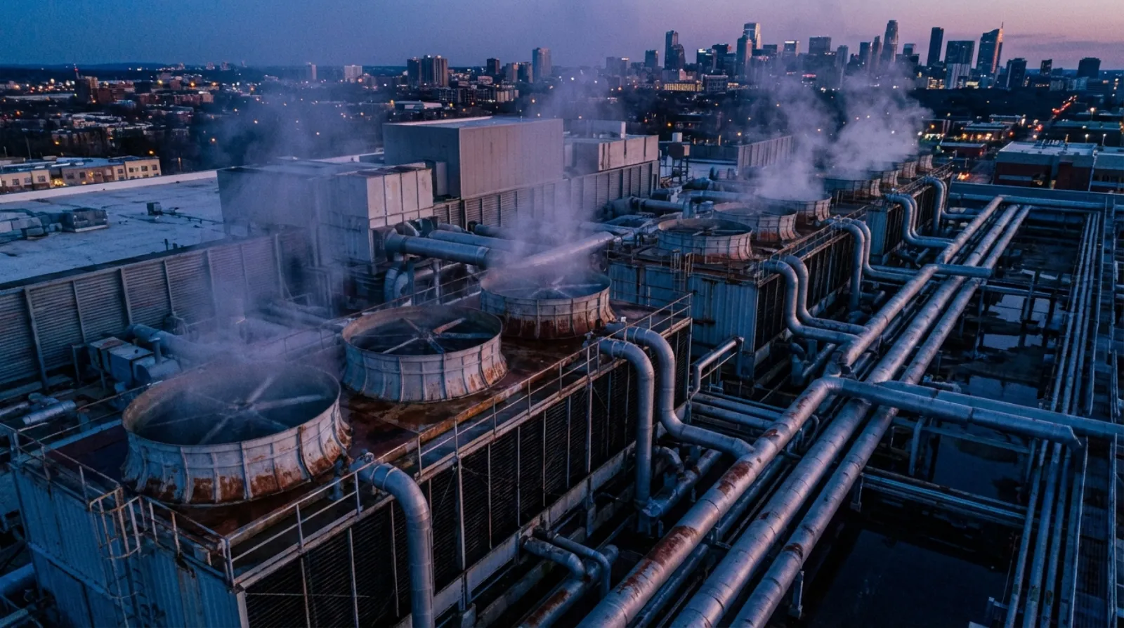
The cooling tower is an indispensable heat rejection device in water-cooled central air conditioning systems, responsible for dissipating the waste heat generated by the chiller condenser to the atmosphere. Cooling tower performance directly affects the condensing temperature, which in turn determines the chiller's compressor power consumption and overall system energy use. However, in engineering practice, cooling tower design and selection often do not receive the same level of attention as the chiller itself, and water quality management is frequently neglected until severe scaling or corrosion problems appear[1]. This article systematically explores the engineering practices of cooling tower type selection, thermal design, water quality management, energy-saving strategies, and preventive maintenance plans, starting from the role of cooling towers in HVAC systems.
1. The Role of Cooling Towers in Central Air Conditioning Systems
In the condenser heat rejection loop of water-cooled central air conditioning systems, the cooling tower plays the critical role of ultimately dissipating system waste heat to the atmosphere. The chiller's condenser condenses high-temperature, high-pressure refrigerant gas into liquid, and the heat released during this process (including the cooling heat absorbed by the evaporator and the heat generated by compressor work) is carried by cooling water to the cooling tower, where it dissipates to the atmosphere through heat and mass transfer between water and air[2].
Cooling tower heat rejection performance directly determines the cooling water return temperature, which in turn affects the chiller condensing temperature. According to the basic principles of the Carnot cycle, for every 1 degree C reduction in condensing temperature, chiller compressor power consumption decreases by approximately 2.5-3.5%, corresponding to a COP improvement of approximately 1.5-2%[3]. This means a well-performing cooling tower is not just a heat rejection device but a critical lever for overall system energy savings. Conversely, when a cooling tower cannot maintain design leaving water temperature due to fill blockage, scaling, or fan efficiency degradation, the resulting increase in condensing pressure leads to significantly higher chiller power consumption, and in severe cases may trigger high-pressure protection trips.
Taking a 1,000-ton chiller system as an example, if the cooling tower leaving water temperature rises from the design value of 32 degrees C to 35 degrees C, condensing temperature increases by approximately 3 degrees C, and chiller power consumption increases by approximately 8-10%. Based on 3,000 annual operating hours and 70% average load factor, the additional electricity cost can reach hundreds of thousands of dollars annually. Therefore, proper cooling tower selection and ongoing maintenance is an extremely important component of HVAC system lifecycle cost management.
2. Cooling Tower Types and Selection
Open Circuit and Closed Circuit
Cooling towers are classified into open circuit and closed circuit types based on how cooling water contacts air. In open circuit cooling towers, cooling water directly contacts air for heat and mass exchange, offering high heat rejection efficiency and lower equipment cost -- this is the most common configuration for central air conditioning systems. Closed circuit cooling towers enclose the cooling water within coils, with spray water covering the coil surface for indirect heat rejection. The cooling water does not directly contact air, effectively reducing water quality contamination and water loss, but with lower heat rejection efficiency and higher equipment volume and cost[4]. Closed circuit cooling towers are suitable for applications requiring strict water quality control or cross-contamination prevention, such as hospitals and semiconductor fab process cooling water systems.
Counterflow and Crossflow
Open circuit cooling towers are further classified by the relative direction of airflow and water flow into counterflow and crossflow types. In counterflow cooling towers, air flows upward from the tower base while cooling water sprays downward from the distribution system above, creating counter-directional contact with maximum heat transfer driving force and highest heat rejection efficiency -- allowing a more compact tower body for the same cooling capacity. However, counterflow towers have air intakes below the fill, requiring higher static pressure and relatively greater fan energy consumption[4].
In crossflow cooling towers, air passes horizontally through the fill, creating cross-directional contact with the top-to-bottom water flow. Crossflow advantages include large air intake area, low fan static pressure, lower noise, and ample maintenance access space, making fill cleaning and replacement more convenient. Disadvantages include larger tower footprint and potential uneven water distribution at low loads that may affect heat rejection efficiency. In central air conditioning applications, small to medium systems (under 500 tons) typically use counterflow, while both types are used in large systems.
Selection Parameters
Cooling tower selection requires the following key parameters[5]:
- Cooling Water Flow Rate: Determined by chiller condenser heat rejection and design temperature difference. General HVAC system cooling water temperature range is 5 degrees C (entering 37 degrees C, leaving 32 degrees C), requiring approximately 0.78 L/s (13.2 GPM/RT) per refrigeration ton
- Entering-Leaving Temperature Difference -- Range: The difference between cooling water entering and leaving tower temperatures, typically 5 degrees C. Greater range means more heat removed per unit of water volume, but also requires greater cooling tower capacity
- Wet-Bulb Temperature: The theoretical limit of cooling tower heat rejection is cooling the water to the entering air wet-bulb temperature. The selected design wet-bulb temperature directly determines cooling tower size and fan configuration
- Approach Temperature: The difference between cooling water leaving temperature and entering air wet-bulb temperature -- the core indicator of cooling tower performance. Typical design values are 3-5 degrees C. Smaller approach means higher cooling tower performance, but required tower area and airflow increase exponentially, with economics declining rapidly
CTI Certification and Selection Software
Cooling tower performance verification should follow the Cooling Technology Institute (CTI) STD-201 standard. CTI certification ensures manufacturer-claimed cooling capacities have been verified through independent third-party testing, preventing selection based on inflated performance data[5]. Major cooling tower manufacturers provide proprietary selection software (such as BAC's BACSmart, Marley's Marley Tech) for quickly screening suitable tower types and configurations based on design conditions. When using these selection tools, engineers should confirm that input design wet-bulb temperature, flow rate, and temperature difference conditions are consistent with the HVAC system design, and require manufacturers to provide CTI-certified performance curves as verification basis.
3. Thermal Design and Engineering Calculations
Design Wet-Bulb Temperature Selection
The starting point for cooling tower thermal design is the selection of design wet-bulb temperature. The ASHRAE Handbook -- Fundamentals provides statistical design conditions for weather stations worldwide. For example, the 0.4% exceedance frequency wet-bulb temperature design value for Kaohsiung is approximately 28.0 degrees C[6]. This means statistically only about 35 hours per year will have wet-bulb temperatures exceeding this value. For general commercial HVAC systems, using the 0.4% design wet-bulb temperature adequately covers the vast majority of operating conditions; critical facilities such as hospitals and data centers may need more conservative design margins.
Notably, the high-humidity climate of southern Taiwan means design wet-bulb temperatures are quite close to dry-bulb temperatures -- summer wet-bulb temperatures in Kaohsiung frequently remain at 27-28 degrees C, making the cooling tower heat rejection driving force (difference between cooling water temperature and wet-bulb temperature) quite limited. Compared to temperate dry climate regions, cooling towers in Taiwan require larger tower sizes and airflow for the same cooling capacity.
Cooling Capacity Calculation
Cooling tower heat rejection capacity is calculated using the following formula[2]:
Q = m × Cp × ΔT
Where Q is heat rejection (kW), m is cooling water mass flow rate (kg/s), Cp is the specific heat of water (4.186 kJ/kg·K), and ΔT is the Range (degrees C). For a 1,000-ton chiller, condenser heat rejection is approximately 1,000 × 3.517 × 1.25 = 4,396 kW (assuming COP = 5.0), requiring a cooling water flow rate of approximately 4,396 / (4.186 × 5) = 210 L/s.
Drift Loss, Evaporation Loss, and Blowdown
Open circuit cooling towers experience three types of water loss during operation[4]:
- Evaporation Loss: This is the primary heat rejection mechanism of the cooling tower. Approximately 1 kg of water evaporates per 2,326 kJ of heat rejected. Evaporation loss is approximately 1-1.5% of circulating water volume (approximately 1% of circulating water per 5.5 degrees C temperature difference)
- Drift Loss: Water droplets entrained by airflow escaping the tower body. Modern high-efficiency drift eliminators can control drift loss to within 0.001-0.005% of circulating water volume
- Blowdown: Cooling water periodically discharged to control cycles of concentration. Blowdown volume depends on water quality management strategy and target cycles of concentration
Cycles of Concentration
Cycles of Concentration (CoC) is the ratio of dissolved solids concentration in cooling water to makeup water concentration. The evaporation process removes only pure water, leaving dissolved solids to continuously concentrate in the circulating water. The CoC setting represents the balance point between water volume management and water quality management[7] -- higher CoC means less blowdown and less makeup water, but also higher calcium and magnesium ion concentrations and correspondingly increased scaling risk. General HVAC system cooling water CoC is controlled between 3-5, with specific values depending on makeup water quality and chemical treatment program capability. Makeup water volume can be calculated as: Makeup = Evaporation Loss + Drift Loss + Blowdown = Evaporation Loss × CoC / (CoC - 1).
4. Water Quality Management: Scale, Corrosion, and Biological Control
The cooling water system is an open water circulation system where cooling water directly contacts large volumes of air in the tower, continuously absorbing atmospheric dust, microbial spores, oxygen, and carbon dioxide, combined with dissolved solids concentration effects from evaporation, making cooling water quality management the most challenging maintenance topic[7].
Scale Formation and Chemical Treatment
Scale formation primarily results from calcium and carbonate ions in cooling water precipitating calcium carbonate (CaCO3) deposits on high-temperature surfaces (particularly condenser tube walls). Scale has extremely high thermal resistance -- just 0.3 mm of calcium carbonate scale can reduce condenser heat transfer efficiency by approximately 10%, causing condensing temperature to rise and chiller energy consumption to increase[3]. Chemical treatment approaches for scale prevention include:
- Scale Inhibitors: Such as phosphate-based and organic phosphonate-based agents, which inhibit scale formation by interfering with calcium carbonate crystal nucleation
- Dispersants: Disperse already-formed small scale particles in the water, preventing them from aggregating and depositing on tube wall surfaces
- pH Control: Water pH is a critical factor affecting scaling tendency. When the Langelier Saturation Index (LSI) is positive, the water has scaling tendency; when negative, it has corrosive tendency. Cooling water pH is generally controlled between 7.0-8.5
Corrosion Control
Corrosion problems in cooling water systems involve multiple mechanisms: oxygen corrosion (dissolved oxygen attacking carbon steel tube walls), galvanic corrosion (dissimilar metal contact), and microbiologically influenced corrosion (sulfate-reducing bacteria producing hydrogen sulfide). Corrosion control strategies include[7]:
- Corrosion Inhibitors: Such as molybdate-based, zinc salt-based, and organic phosphonate-based agents that form protective films on metal surfaces to block corrosive media
- pH Management: Maintaining cooling water pH in the slightly alkaline range (7.5-8.5) to reduce acidic corrosion tendency while avoiding scaling problems from excessively high pH
- Conductivity Control: Using automatic blowdown valves to keep cooling water conductivity within target values (generally below 1,500 uS/cm) to avoid accelerated corrosion from high dissolved solids
Legionella Risk and Prevention
Legionnaires' Disease is a severe pneumonia caused by Legionella pneumophila, and cooling towers are a known primary transmission source. Legionella bacteria proliferate extensively in warm water environments between 25-45 degrees C and spread through cooling tower drift aerosols into surrounding air, potentially infecting people who inhale bacteria-containing droplets[8]. ASHRAE Guideline 12-2020, Minimizing the Risk of Legionellosis Associated with Building Water Systems, provides a complete Legionella risk management framework with core recommendations including:
- Establish a written Water Management Program covering risk assessment, control measures, monitoring procedures, and corrective actions
- Maintain effective residual biocide concentration in cooling water -- free chlorine maintained at 0.5-1.0 ppm, or periodic shock dosing with non-oxidizing biocides
- Perform periodic Legionella culture testing (recommended quarterly); when colony counts exceed 1,000 CFU/L, enhanced disinfection procedures should be initiated
- After cooling tower shutdown exceeding three days, disinfection treatment should be performed before restarting
- Install high-efficiency drift eliminators to control drift rate to within 0.002%, reducing aerosol transmission risk
Taiwan's Indoor Air Quality Management Act and related environmental regulations are also progressively strengthening requirements for cooling tower Legionella management. Building management entities should incorporate Legionella prevention into routine water quality management operations[9].
Automatic Chemical Feed and Water Quality Monitoring Systems
Modern cooling water treatment systems are highly automated. Automatic chemical feed systems use online sensors such as conductivity meters, pH meters, and ORP (Oxidation-Reduction Potential) meters to monitor water quality in real-time, automatically controlling chemical dosing rates and blowdown volumes based on setpoints. Advanced systems also integrate remote monitoring and data logging functions, allowing water treatment service providers to monitor water quality status in real-time through cloud platforms and remotely adjust dosing parameters. Conductivity-controlled blowdown is the most basic automated function -- when cooling water conductivity exceeds the setpoint (indicating excessive CoC), the blowdown valve automatically opens to discharge high-concentration water and admit fresh makeup water.
Need cooling tower selection consulting or water quality management improvement solutions? Contact our engineering team for professional system diagnostics and optimization recommendations.
5. Energy-Saving Strategies and VFD Control
Variable Frequency Fan Control Strategies
Cooling tower fan energy consumption accounts for approximately 5-8% of total central air conditioning system energy use. Traditional constant-speed fans can only be controlled by on/off switching, causing large cooling water temperature fluctuations and unnecessary energy waste. Variable Frequency Drives (VFD) enable continuous fan speed adjustment based on actual heat rejection demand, delivering significant energy savings[3]. According to the Fan Affinity Laws, fan power is proportional to the cube of speed -- when fan speed drops to 80%, power consumption is only 51% of rated; when speed drops to 60%, power is only 22% of rated.
VFD fan control strategies typically target tracking the condensing temperature setpoint. The controller adjusts fan speed through a PID control loop based on the deviation between cooling water leaving temperature and setpoint. In systems with multiple cooling towers operating in parallel, an equal-loading control strategy should be adopted -- all operating cooling tower fans maintain the same speed rather than some at full speed and others off, maximizing overall fan efficiency[10].
Free Cooling Mode
Free cooling leverages lower outdoor wet-bulb temperatures during winter or transitional seasons to produce low-temperature cooling water from the cooling tower to replace or partially replace chiller operation. When outdoor wet-bulb temperature falls below a threshold (typically 2-3 degrees C below chilled water return temperature), the cooling tower can produce sufficiently cool water, transferring cooling capacity to the chilled water side through a plate heat exchanger, achieving cooling without running the chiller[3]. In southern Taiwan (such as Kaohsiung), winter wet-bulb temperatures are approximately 16-20 degrees C. While free cooling available hours are fewer than in temperate regions, for data centers, 24-hour industrial processes, and other facilities with year-round cooling demand, considerable energy savings can still be achieved.
Cooling Water Temperature Reset Strategy
Traditional cooling water temperature control uses a fixed setpoint (such as 32 degrees C leaving temperature), but under partial load or low outdoor wet-bulb temperature conditions, the cooling tower can easily achieve lower leaving water temperatures. Cooling water temperature reset strategy dynamically adjusts the cooling water temperature setpoint based on real-time outdoor wet-bulb temperature, allowing condensing temperature to decrease accordingly and improving chiller efficiency. A typical reset strategy is: cooling water leaving temperature setpoint = outdoor wet-bulb temperature + fixed approach (such as 3 degrees C), with upper and lower limits set (such as upper limit 32 degrees C, lower limit 18 degrees C)[10]. When implementing cooling water temperature reset, care must be taken regarding the chiller's minimum condensing pressure limitation to avoid abnormal operation from excessively low cooling water temperatures.
6. Preventive Maintenance Plan
The cooling tower is equipment simultaneously subjected to thermal stress, water chemistry corrosion, biological contamination, and UV degradation. Without a systematic maintenance plan, its performance degradation rate will be far faster than other HVAC equipment. A comprehensive preventive maintenance plan should cover the following items[4]:
Routine Maintenance (Daily/Weekly)
- Visual inspection of cooling tower operating status: normal fan operation, no abnormal vibration or noise
- Check basin water level and makeup water float valve operation
- Record cooling water entering and leaving temperatures, conductivity, and pH
- Confirm automatic chemical feed system chemical inventory and dosing status
- Remove visible solid debris and sediment from the basin
Monthly Maintenance
- Inspect and clean basin strainer and side-stream filter
- Check distribution nozzle water flow uniformity, clear blocked nozzles
- Inspect fan belt (belt-drive models) tension and wear condition
- Calibrate water quality monitoring instruments (conductivity meter, pH meter, ORP meter)
- Perform Legionella rapid testing (per water management plan schedule)
Annual Maintenance (Overhaul)
- Thoroughly clean fill (film fill), removing biofilm, algae, and sediment. Severe blockage may require high-pressure water jetting or chemical soaking
- Inspect drift eliminator integrity, replace deformed or damaged eliminator blades
- Comprehensive fan assembly inspection: blade balance, gear reducer oil level and quality, bearing lubrication, motor insulation resistance measurement
- Structural component inspection: FRP shell for cracks or degradation, galvanized steel frame for corrosion, bolts for loosening
- Basin anti-corrosion coating inspection and repair
- Drain valve, overflow pipe, makeup water piping and fittings inspection and replacement
Fill Replacement and Cleaning Cycle
Cooling tower fill is the core component for heat rejection performance, with a typical service life of 8-15 years depending on water quality management quality and fill material. PVC fill under good water quality management can maintain 10-15 years of service life, but if algae growth is severe or sediment accumulates, fill passages gradually become blocked, dramatically reducing heat transfer area and efficiency. At least annual visual inspection and pressure washing of fill is recommended, with periodic (every 3-5 years) heat rejection performance testing compared to initial performance curves to assess fill degradation[5].
Structural Corrosion Inspection
Cooling tower structural components are continuously exposed to high-temperature, high-humidity corrosive environments, with carbon steel and galvanized steel materials being particularly susceptible to corrosion. FRP (Fiber Reinforced Plastic) and stainless steel structural components offer better corrosion resistance but at higher cost. Periodic structural corrosion inspection should include: galvanized layer integrity (checking for blistering or peeling), weld point corrosion status, basin bottom corrosion depth measurement, and support structure strength assessment.
Winter Shutdown Maintenance
For HVAC systems that do not operate cooling towers in winter, shutdown maintenance procedures include: draining all water from basins and piping to prevent freeze damage (this risk is lower in southern Taiwan, but draining is still necessary to avoid standing water breeding Legionella), cleaning fill and basin, lubricating all mechanical components, and covering air intakes with dust covers to reduce UV degradation. Before spring restart, comprehensive inspection, disinfection treatment, and trial operation should be conducted to confirm all functions are normal before commissioning for regular operation.
Conclusion
The cooling tower may appear to be merely a "passive" heat rejection device in the HVAC system, but in reality, the precision of its selection and design, the rigor of its water quality management, and the thoroughness of its maintenance directly and profoundly affect overall system energy efficiency, operational reliability, and public health safety. Particularly under Taiwan's high-temperature, high-humidity climate conditions, cooling tower design margins are limited, water quality degradation is rapid, and Legionella growth risk is high -- these challenges all demand that engineers approach every aspect of cooling towers with greater professionalism, from precise thermal calculations during the selection phase, to automated water quality management during operation, to comprehensive preventive maintenance during annual overhauls. Only by treating the cooling tower as core equipment equal in importance to the chiller can the overall system's optimal performance be truly achieved.