Modern buildings pursue high airtightness and high insulation to reduce HVAC loads, but this simultaneously cuts off natural ventilation pathways. In sealed spaces, CO₂ concentrations rise, formaldehyde and TVOC accumulate, and pathogens linger — these problems are not automatically solved by having sufficiently cold air conditioning. Energy Recovery Ventilators (ERVs) recover energy between exhaust and supply air, dramatically reducing HVAC energy consumption while introducing fresh outdoor air, making them the core equipment in contemporary building ventilation design. This article provides a complete engineering practice guide covering working principles, sizing calculations, and system design.
1. Why Are Energy Recovery Ventilators Needed?
1.1 The Ventilation Dilemma of Sealed Buildings
Taiwan's building energy codes (EEWH green building label and Building Technical Regulations) encourage improving envelope insulation and airtightness to reduce HVAC thermal loads. However, the more airtight a building becomes, the lower its natural ventilation rate. When fresh air supply per person per hour is insufficient, indoor pollutant concentrations continue to rise[1].
Taiwan's Indoor Air Quality Management Act specifies that the 8-hour average CO₂ concentration in designated premises must not exceed 1,000 ppm[2]. However, in practical inspections, many office buildings, cram schools, and department stores frequently exceed this limit during peak hours, with the root cause being insufficient outdoor air intake.
1.2 The Energy Cost of Outdoor Air Intake
Taking Kaohsiung as an example, typical summer outdoor conditions are 34°C / 75% RH (enthalpy approximately 97 kJ/kg), with indoor design conditions of 26°C / 55% RH (enthalpy approximately 55 kJ/kg), requiring an enthalpy difference of 42 kJ per kilogram of outdoor air to process. For a 500-person office building introducing outdoor air per ASHRAE 62.1 (approximately 5,000 CMH), the cooling load for outdoor air processing alone approaches 20 refrigeration tons — equivalent to 25–30% of the entire building's HVAC load[3].
This is precisely the value of the energy recovery ventilator: it allows buildings to "breathe" without paying the full energy cost.
2. How Energy Recovery Ventilators Work
2.1 Sensible Heat Recovery vs. Total Heat Recovery
Energy recovery ventilation equipment is divided into two major categories based on the type of energy recovered:
- Heat Recovery Ventilator (HRV): Recovers only sensible heat caused by temperature differences. Exhaust heat energy is transferred to supply air through metal or plastic plates, but water vapor (latent heat) is not exchanged. HRVs are suitable for dry or cold climates, or locations requiring strict humidity isolation (such as swimming pools and laboratories).
- Energy Recovery Ventilator (ERV): Recovers both sensible and latent heat simultaneously. Its core element uses special moisture-permeable membranes or molecular sieve materials, allowing both temperature and moisture molecules to exchange between exhaust and supply air. ERVs are particularly suitable for hot and humid climates, as latent heat typically accounts for 50–70% of outdoor air processing load[4].
In southern Taiwan's summer, for example, of the 42 kJ/kg outdoor air enthalpy difference, the latent heat portion accounts for approximately 28 kJ/kg (67%). Using only an HRV for sensible heat recovery significantly diminishes the energy-saving effect. Therefore, under Taiwan's climate conditions, an ERV is virtually the only sensible choice.
2.2 Types of Heat Exchange Elements
The core elements of energy recovery ventilators come in three main types:
- Cross-flow plate: Exhaust and supply air flow at 90° angles across stacked moisture-permeable membrane plates. Simple construction, no moving parts, low maintenance costs, but theoretical maximum efficiency is limited to approximately 75%. Suitable for small to medium systems (airflow 150–2,000 CMH).
- Counter-flow plate: Exhaust and supply air flow at 180° in opposite directions, increasing effective heat transfer area, with theoretical efficiency exceeding 90%. Larger in size, mostly used for large systems or high-efficiency requirements.
- Rotary wheel: A heat storage wheel rotates alternately between exhaust and supply air streams to transfer energy. High efficiency (80–85%), but with 3–5% cross-contamination risk of exhaust mixing into supply air, making it unsuitable for hospital negative pressure isolation rooms or other locations with strict airflow direction requirements[5].
2.3 Applicability Considerations for Taiwan's High-Humidity Climate
With Taiwan's annual average relative humidity exceeding 75%, and frequently reaching 85–95% during the plum rain season and summer, energy recovery ventilator design must pay special attention to:
- Moisture-permeable membrane durability: In long-term high-humidity environments, low-quality membranes may swell, deform, or develop mold growth, leading to efficiency degradation and hygiene concerns. Products verified through high-humidity durability testing (such as JIS B 8628) should be selected.
- Drainage design: When high-humidity outdoor air enters the ERV, some water vapor may condense. A condensate drain pan and drain pipe must be installed beneath the element to prevent water accumulation and bacterial growth.
- Anti-mold treatment: Heat exchange elements and the interior of the unit should use antibacterial and anti-mold materials or coatings to ensure long-term hygienic safety.
3. Energy Recovery Ventilator Sizing Calculations
3.1 Outdoor Air Requirement Calculation (ASHRAE 62.1)
The airflow selection for an energy recovery ventilator must first be based on the minimum outdoor air requirement calculated using the Ventilation Rate Procedure from ASHRAE Standard 62.1[1]:
Vbz = Rp × Pz + Ra × Az
- Rp: Outdoor air rate per person (L/s·person)
- Pz: Design number of occupants
- Ra: Outdoor air rate per unit area (L/s·m²)
- Az: Space area (m²)
For a 200 m², 20-person office space (Rp = 2.5 L/s·person, Ra = 0.3 L/s·m²): Vbz = 2.5 × 20 + 0.3 × 200 = 110 L/s = 396 CMH. The ERV's rated airflow should at least cover this requirement, with a 10–15% margin.
3.2 Key Specification Parameters
Core specifications to compare during selection include:
- Rated airflow (CMH): Must exceed the calculated outdoor air requirement. Note that rated airflow is typically at zero static pressure conditions; actual installed airflow will decrease due to duct resistance.
- External static pressure (Pa): The ERV's ability to overcome external duct resistance. Residential short-duct systems typically need 50–80 Pa, while commercial building long-duct systems may require 150–250 Pa or more. Insufficient static pressure will result in severely inadequate actual airflow.
- Total heat exchange efficiency (%): Per AHRI 1060 or JIS B 8628 test standards[6]. Quality products should have total heat efficiency between 70–85%. Note the efficiency test conditions (airflow, temperature and humidity difference) stated by manufacturers, and verify whether it is an "equal airflow" test condition.
- Noise level (dB(A)): Residential applications recommend unit noise ≤ 35 dB(A), office spaces ≤ 40 dB(A). Silencer boxes or silencer flex ducts can further reduce noise during installation.
3.3 Enthalpy Difference Method for Energy Savings Estimation
The energy savings of an ERV can be precisely calculated using the enthalpy difference method. For the Kaohsiung area:
- Outdoor design conditions: 34°C / 75% RH → enthalpy h₁ ≈ 97 kJ/kg
- Indoor design conditions: 26°C / 55% RH → enthalpy h₂ ≈ 55 kJ/kg
- Enthalpy difference: Δh = 97 − 55 = 42 kJ/kg
- Total heat exchange efficiency η = 75%
- Recovered enthalpy difference: 42 × 0.75 = 31.5 kJ/kg
- Outdoor airflow Q = 5,000 CMH ≈ 1.67 kg/s
- Recovered cooling capacity: 1.67 × 31.5 = 52.6 kW ≈ 15 RT
With a chiller COP of 4.5, the recovered cooling capacity is equivalent to saving 11.7 kW of compressor electricity. With 2,000 summer full-load operating hours, annual electricity savings are approximately 23,400 kWh. At an electricity rate of NT$4.5/kWh, over NT$100,000 in electricity costs can be saved annually[7].
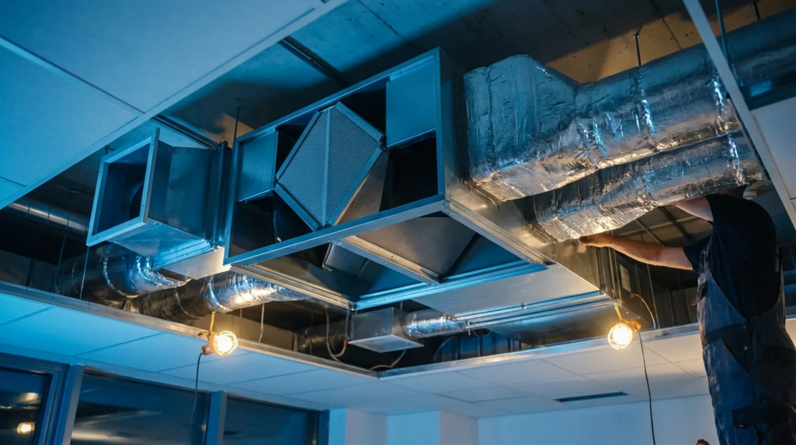
4. System Design and Installation Guidelines
4.1 Dedicated Outdoor Air System vs. HVAC Integration
There are two main approaches for integrating energy recovery ventilators:
- Dedicated Outdoor Air System (DOAS): The ERV independently handles outdoor air, delivering processed fresh air directly to indoor spaces or to the return air side of zone fan coil units (FCUs). Advantages include precise outdoor air volume control unaffected by indoor HVAC operating modes; disadvantages include the need for an independent duct system.
- AHU Integration: The ERV is installed in the outdoor air intake section of the air handling unit, with exhaust taken from the AHU return air or indoor exhaust outlets. Advantages include system simplicity and space savings, but the ERV operation is linked with the AHU, offering less flexibility.
For new construction, DOAS paired with an ERV is currently the internationally recognized best practice, especially in locations requiring precise indoor environmental quality control, such as hospitals, laboratories, and premium office buildings[8].
4.2 Duct Layout Principles
An ERV has four air ports: outdoor air intake (OA), supply air (SA), return air (RA), and exhaust air (EA). Duct layout is critical to system performance:
- Intake and exhaust port spacing: The outdoor air intake and exhaust ports should be at least 1.5 meters apart, and the exhaust port should be on the downwind side of the intake port to prevent exhausted contaminated air from being re-ingested (short-circuiting).
- Supply and return air separation: Indoor supply and return air ports should be placed at diagonal positions in the space, ensuring fresh air thoroughly sweeps through the occupied zone before being recovered, preventing newly supplied air from being immediately drawn back.
- Duct length and bends: Longer ducts with more bends result in greater pressure loss. Design should minimize duct path lengths, reduce 90° elbows, and use turning vane elbows where necessary to reduce resistance.
- Duct insulation: Outdoor air intake ducts carry hot and humid air in summer, and condensation may occur on the outer surface. All ducts passing through non-air-conditioned zones should be wrapped in insulation to prevent condensate dripping and ceiling water damage.
4.3 Avoiding Airflow Short-Circuiting
Airflow short-circuiting is the most common design flaw in ERV installations. Once short-circuiting occurs, the system's actual ventilation effectiveness is drastically reduced, rendering it virtually useless:
- External short-circuiting: Contaminated air from the exhaust port is drawn into the intake port. Solutions: increase intake/exhaust port spacing, consider prevailing wind direction, install deflectors on the exhaust port.
- Internal short-circuiting: Indoor supply and return ports are too close together, with fresh air being recovered before passing through the occupied zone. Solutions: place supply and return ports at opposite ends of the space, or adopt a top-supply, bottom-return airflow pattern.
4.4 Filter Grade Selection (MERV Rating)
The filter grade on the intake side of an ERV directly affects indoor air quality. Per the MERV rating in ASHRAE 52.2[9]:
- MERV 8 (Pre-filter): Filters 3–10 μm particles, with limited PM2.5 filtration effectiveness, suitable only for general residences in areas with good air quality.
- MERV 13 (Medium-efficiency): Filters 75–85% of 0.3–1.0 μm particles, recommended by ASHRAE as the minimum filter grade for commercial buildings. For most areas in Taiwan, MERV 13 is a practical choice.
- MERV 16 (High-efficiency) / HEPA: Filtration efficiency ≥ 95% (0.3 μm), suitable for healthcare facilities, cleanrooms, and other high-requirement locations. However, air resistance increases significantly, requiring higher static pressure fans.
When selecting filter grades, the ERV fan's static pressure capability must also be considered. Installing high-efficiency filters without upgrading the fan results in severely insufficient airflow that fails to meet indoor ventilation standards.
Planning a building ventilation and energy recovery system? Contact our engineering team for professional sizing recommendations and system design solutions tailored to your facility conditions.
5. Application Cases for Different Building Types
5.1 Office Buildings
Office buildings are the most typical application for ERVs. For a commercial office building with 5,000 m² floor area and 500 design occupants:
- Outdoor air requirement: Approximately 5,000 CMH per ASHRAE 62.1 calculation
- System configuration: 1–2 large ERVs (1,500–2,500 CMH) per floor, with independent fresh air ducts delivered to the return air side of zone FCUs
- Filter grade: MERV 13, combined with DCV (Demand-Controlled Ventilation) system, adjusting outdoor air volume based on zone CO₂ sensor readings
- Energy savings: Estimated at Kaohsiung climate conditions, ERVs can save approximately 15–20% of HVAC energy consumption annually
5.2 Healthcare Facilities
Healthcare facilities have extremely strict ventilation requirements, with ASHRAE 170[10] specifying air change rates and pressure relationships for various healthcare spaces. ERV applications in healthcare settings require special attention:
- Cross-contamination prevention: Rotary wheel ERVs are strictly prohibited; only plate-type ERVs (with no cross-contamination risk) may be used
- Pressure control: Infection isolation rooms must maintain negative pressure, and the ERV intake/exhaust airflow ratio must be precisely controlled
- Filter grade: At least MERV 14 on the intake side, with HEPA supplementation in some areas
- Applicable areas: Primarily installed in outpatient areas, waiting rooms, and administrative offices; operating rooms and isolation rooms typically use 100% outdoor air systems without energy recovery
5.3 School Classrooms
School classrooms have high occupancy density (typically 30–40 persons per room), and CO₂ concentration exceedance is the most common indoor air quality issue. ERV applications in schools offer clear economic benefits:
- Outdoor air requirement: A 60 m², 40-person classroom requires approximately 450 CMH per ASHRAE 62.1
- Equipment selection: One 500 CMH class ERV per classroom, ceiling-mounted within the ceiling plenum
- Filter grade: MERV 13 effectively filters outdoor PM2.5, protecting student respiratory health
- Control strategy: Combined with CO₂ sensors, full-speed operation during class hours, low-speed standby during breaks, balancing IAQ and energy efficiency
5.4 Residential Buildings
In recent years, demand for ERVs in premium residential buildings has grown rapidly. Residential application design considerations differ from commercial buildings:
- Noise control: Residences are extremely noise-sensitive; unit noise should be controlled below 30 dB(A), with silencer flex ducts to reduce wind noise
- Aesthetic integration: Supply and return outlet positions and sizes must be integrated with interior design to avoid impacting ceiling aesthetics
- Airflow distribution: For a typical three-bedroom residence, total airflow is approximately 200–300 CMH. Fresh air is delivered to the living room and bedrooms, while return air is drawn from the kitchen and bathrooms, utilizing door gaps or transfer grilles to create a unidirectional airflow path from clean zones to contaminated zones
- Maintenance accessibility: Filter access panels should be placed in easily accessible locations to avoid requiring ceiling removal for maintenance
6. Maintenance Management and Common Issues
6.1 Filter Replacement Intervals
Filters are the fastest-wearing component in an ERV and the first line of defense for maintaining system performance:
- Pre-filters (MERV 8 and below): Recommended cleaning or replacement every 1–3 months, depending on environmental pollution levels
- Medium-efficiency filters (MERV 13): Recommended replacement every 3–6 months. Clogged filters lead to reduced airflow and increased fan energy consumption
- Differential pressure monitoring: Professional systems should install pre/post-filter differential pressure gauges, with replacement needed when differential pressure exceeds twice the initial value, rather than relying solely on time-based schedules
6.2 Heat Exchange Element Efficiency Degradation
The core component of an ERV — the heat exchange membrane or wheel — will gradually decline in efficiency with prolonged use:
- Contamination accumulation: Dust, grease, and microorganisms adhering to membrane surfaces reduce heat transfer and moisture permeability. Regular cleaning (at least annually) can slow degradation.
- Material aging: After years of use, polymer materials in moisture-permeable membranes may become brittle or lose permeability. The recommended service life for heat exchange elements is generally 7–10 years.
- Efficiency testing: It is recommended to commission professional engineers to measure intake/exhaust temperature and humidity every two years, calculating actual total heat exchange efficiency and comparing with original specifications to assess element condition.
6.3 Condensation and Frost Prevention
Although Taiwan's winters are relatively mild, condensation or even frosting may still occur on the exhaust side of ERVs during cold periods in northern and mountainous areas:
- Condensation mechanism: Cold outdoor air entering the ERV pulls exhaust-side temperatures below the dew point, causing water vapor to condense in the exhaust passage.
- Frost risk: When outdoor air temperature drops below 0°C with high exhaust moisture content, condensed water freezes, blocking exhaust passages and causing sudden airflow reduction or equipment shutdown.
- Prevention measures: Install preheat coils or electric heaters to preheat outdoor air above 0°C; use bypass dampers to temporarily bypass the heat exchange element when outdoor air temperature is too low; or use controllers with defrost functions that periodically switch operating modes for defrosting.
Conclusion
An energy recovery ventilator is not just a piece of equipment, but a complete ventilation engineering solution. From outdoor air volume calculation, equipment sizing, duct layout to filter grade selection, every step is interconnected. Under Taiwan's hot and humid climate conditions, ERV-type energy recovery ventilators are the best engineering approach for balancing indoor air quality with HVAC energy efficiency. However, improper sizing, careless installation, or neglected maintenance can render the entire system ineffective.
Professional HVAC engineers can provide comprehensive ventilation planning from the design stage based on building characteristics, usage requirements, and climate conditions — this is the key to ensuring energy recovery ventilators deliver maximum benefits.